
C.1 Preparation for Approach.
 As the distance between a person and the exposed energized conductors or circuit parts decreases, the potential for electrical accident increases.
C.1.1 Unqualified Persons, Safe Approach Distance. Unqualified persons are safe when they maintain a distance from the exposed energized conductors or circuit parts, including the longest conductive object being handled, so that they cannot contact or enter a specified air insulation distance to the exposed energized electrical conductors or circuit parts. This safe approach distance is the limited approach boundary. Further, persons must not cross the arc flash boundary unless they are wearing appropriate personal protective clothing and are under the close supervision of a qualified person. Only when continuously escorted by a qualified person should an unqualified person cross the limited approach boundary. Under no circumstance should an unqualified person cross the restricted approach boundary, where special shock protection techniques and equipment are required.
C.1.2 Qualified Persons, Safe Approach Distance. C.1.2.1 Determine the arc flash boundary and, if the boundary is to be crossed, appropriate arc-rated protective equipment must be utilized. C.1.2.2 For a person to cross the limited approach boundary and enter the limited space, he or she must be qualified to perform the job/task.
C.1.2.3 To cross the restricted approach boundary and enter the restricted space, qualified persons must do the following: (1) Have a plan that is documented and approved by authorized management (2) Use personal protective equipment that is appropriate for working near exposed energized conductors or circuit parts and is rated for the voltage and energy level involved (3) Be certain that no part of the body enters the prohibited space (4) Minimize the risk from inadvertent movement by keeping as much of the body out of the restricted space as possible, using only protected body parts in the space as necessary to accomplish the work.
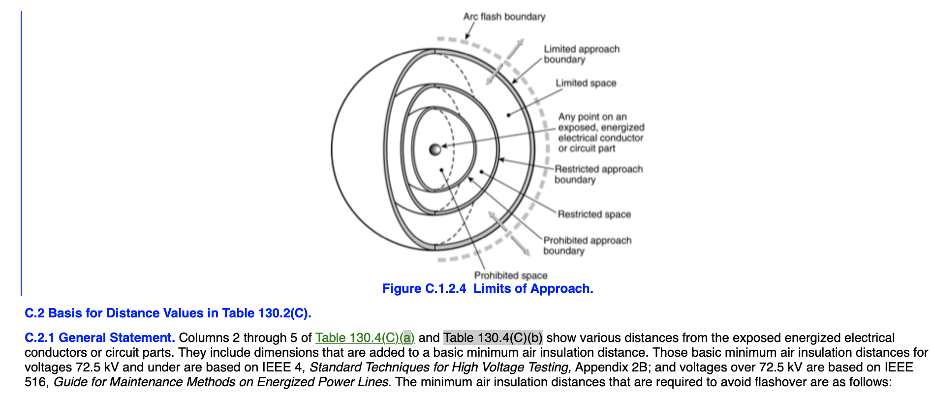
C.1.2.4 Crossing the prohibited approach boundary and entering the prohibited space is considered the same as making contact with exposed energized conductors or circuit parts. (See Figure C.1.2.4.) Therefore, qualified persons must do the following: (1) Have specified training to work on energized conductors or circuit parts (2) Have a documented plan justifying the need to work that close to exposed energized conductors or circuit parts (3) Perform a risk analysis (4) Have the plan and the risk analysis approved by authorized management (5) Use personal protective equipment that is appropriate for working on exposed energized conductors or circuit parts and is rated for the voltage and energy level involved g70e-13_2012.png
Figure C.1.2.4 Limits of Approach. C.2 Basis for Distance Values in Table 130.2(C). C.2.1 General Statement. Columns 2 through 5 of Table 130.4(C)(a) and Table 130.4(C)(b) show various distances from the exposed energized electrical conductors or circuit parts. They include dimensions that are added to a basic minimum air insulation distance. Those basic minimum air insulation distances for voltages 72.5 kV and under are based on IEEE 4, Standard Techniques for High Voltage Testing, Appendix 2B; and voltages over 72.5 kV are based on IEEE 516, Guide for Maintenance Methods on Energized Power Lines. The minimum air insulation distances that are required to avoid flashover are as follows:
(1) ≤300 V: 1 mm (0 ft 0.03 in.) (2) >300 V to ≤750 V: 2 mm (0 ft 0.07 in.) (3) >750 V to ≤2 kV: 5 mm (0 ft 0.19 in.) (4) >2 kV to ≤15 kV: 39 mm (0 ft 1.5 in.) (5) >15 kV to ≤36 kV: 161 mm (0 ft 6.3 in.) (6) >36 kV to ≤48.3 kV: 254 mm (0 ft 10.0 in.) (7) >48.3 kV to ≤72.5 kV: 381 mm (1 ft 3.0 in.) (8) >72.5 kV to ≤121 kV: 640 mm (2 ft 1.2 in.) (9) >138 kV to ≤145 kV: 778 mm (2 ft 6.6 in.) (10) >161 kV to ≤169 kV: 915 mm (3 ft 0.0 in.) (11) >230 kV to ≤242 kV: 1.281 m (4 ft 2.4 in.) (12) >345 kV to ≤362 kV: 2.282 m (7 ft 5.8 in.) (13) >500 kV to ≤550 kV: 3.112 m (10 ft 2.5 in.) (14) >765 kV to ≤800 kV: 4.225 m (13 ft 10.3 in.)
C.2.1.1 Column 1. The voltage ranges have been selected to group voltages that require similar approach distances based on the sum of the electrical withstand distance and an inadvertent movement factor. The value of the upper limit for a range is the maximum voltage for the highest nominal voltage in the range, based on ANSI/IEEE C84.1, Electric Power Systems and Equipment— Voltage Ratings (60 Hz). For single-phase systems, select the range that is equal to the system’s maximum phase-to-ground voltage multiplied by 1.732. C.2.1.2 Column 2. The distances in this column are based on OSHA’s rule for unqualified persons to maintain a 3.05 m (10 ft) clearance for all voltages up to 50 kV (voltage-to-ground), plus 102 mm (4.0 in.) for each 1 kV over 50 kV.
C.2.1.3 Column 3. The distances in this column are based on the following: (1) ≤750 V: Use NEC Table 110.26(A)(1), Working Spaces, Condition 2, for the 151 V to 600 V range. (2) >750 V to ≤145 kV: Use NEC Table 110.34(A), Working Space, Condition 2. (3) >145 kV: Use OSHA’s 3.05 m (10 ft) rules as used in Column 2. C.2.1.4 Column 4. The distances in this column are based on adding to the flashover dimensions shown above the following inadvertent movement distance: ≤300 V: Avoid contact.
Based on experience and precautions for household 120/240-V systems: >300 V to ≤750 V: Add 304.8 mm (1 ft 0 in.) for inadvertent movement. These values have been found to be adequate over years of use in ANSI/IEEE C2, National Electrical Safety Code, in the approach distances for communication workers. >72.5 kV: Add 304.8 mm (1 ft 0 in.) for inadvertent movement. These values have been found to be adequate over years of use in the National Electrical Safety Code in the approach distances for supply workers.
C.2.1.5 Column 5. The distances in this column are based on the following: (1) ≤300 V: Avoid contact. (2) >300 to ≤750 V: Use NEC Table 230.51(C), Clearances. Between open conductors and surfaces, 600 V not exposed to weather. (1) >750 V to ≤2.0 kV: Select value that fits in with adjacent values. (2) >2 kV to ≤72.5 kV: Use NEC Table 490.24, Minimum Clearance of Live Parts, outdoor phase-to-ground values. (3) >72.5 kV: Add 152.4 mm (0 ft 6 in.) for inadvertent movement. These values have been found to be adequate over years of use where there has been a hazard/risk analysis, either formal or informal, of a special work procedure that allows a closer approach than that permitted by the restricted approach boundary distance.